Cellular circuit simulation (#240)
Inspired by grid worlds, non-linear notation and two-dimensional esolangs, I have attempted to design a few ASCII-art languages myself, none satisfactory enough for publication. Without the toolchain to interact in a non-typewriter manner — both on the software as well as on the hardware side — paired with the need for an apt encoding to facilitate higher-order capabilities, I could not manage to create something which stands on its own feet as a proper language, as opposed to nothing more than a convoluted yet primitive processor emulator.
In the fall of 2020, when I was tasked to teach elementary binary semantics courtesy of a brand new mandatory lecture at my university — constructing half-adders from basic gates and combining them to build full adders —, I thought that exactly this bare-bones grid world might be a fruitful endeavor for constructing and combining gates with a visualization of the entropy’s movement across the circuit (one might foolishly think of a bit meandering across a wire, although this interpretation has no physical merit to it).
Within a few hours, I had managed to settle on a grid world definition together with an under 200 lines long interpreter for it. As I opted for an ASCII-CLI-look — significantly boosting development time —, I added image output facilities for this blog post (for which I swiftly designed a few pixel glyphs; only those used by the grid world), avoiding the need to take screenshots of my terminal emulator.
Source: cellular-circuit-simulation.cpp, building: Makefile
Circuits: cellular-circuit-simulation_adder.circuit, cellular-circuit-simulation_odometer.circuit, cellular-circuit-simulation_spiral.circuit
The grid world
As in most grid worlds, non-inert characters are kept to a minimum: there are two entropy sources 0 and 1, the unary negation gate ! and three binary gates &, | and ^. All other characters except the space allow entropic bits to replicate, the special jumpers < and > allow to cross a gap of three characters, rendering interleaving wires possible.
Designing a 3-bit adder
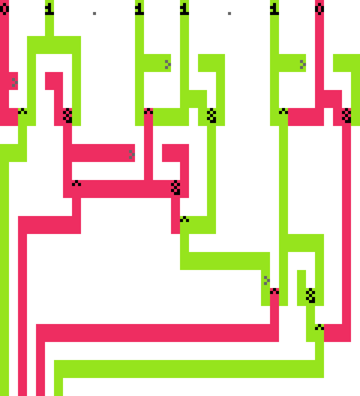
0b110 + 0b011 == 0b1001 using a 3-bit adder (input bits are interleaved, less significant bits reside on the left).-=-
An 𝑛-bit adder performs the complete addition of two 𝑛-bit integers, yielding a (𝑛 + 1)-bit integer. It can be realized by chaining 𝑛 full adders, each comprised of two half adders. For the least significant bit, the carry in can be assumed to be zero and optimized away, the most significant bit’s carry can directly be used as output. As such, the above figure shows - 3 + 3 · 5 = 12 gates, forming a 3-bit adder.
Further circuits
A simpler task than adding two integers is incrementing a single one. This tasks boils down to trickling a singular carry bit, with the least significant bit always flipping:
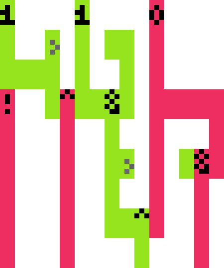
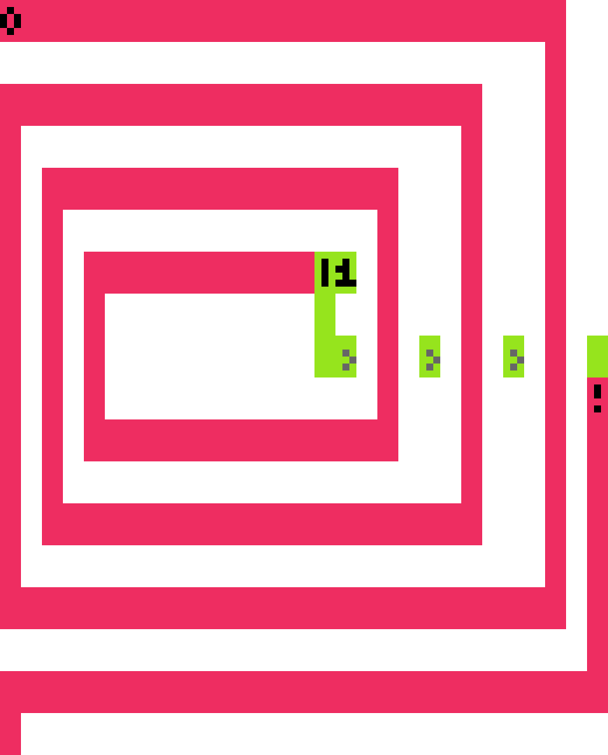
++(0b011) == 0b0100 (less significant bits reside on the left).Of course, one can also explore two-dimensional space without realizing any meaningful computation: